
Explainer
Technical Illustration for Technical Manuals
The Meaning
Accurate First, Readable Always
A technical illustration is judged by one test: can the reader do the task with it. That makes it a different discipline from product or marketing art. The illustrator starts from the engineering (a drawing, a model, or the hardware itself) and takes detail away until only what the task needs is left: the part, its neighbors, its fasteners, and the way in.
In technical manuals the figure and the text are written together. A procedure step names an item by its index number; the figure shows that number on the part; the parts catalog lists the same number with its part number. When any one of the three changes, the other two have to follow, which is why illustration is a managed deliverable in a publications program, not decoration.
Styles
Six Styles, Six Questions
Manuals rely on a small set of styles, each answering a different question for the reader:
- Exploded view
- The assembly pulled apart along its axes so every part is visible in its relationship to the others. The standard view for parts catalogs and for assembly and disassembly procedures.
- Cutaway
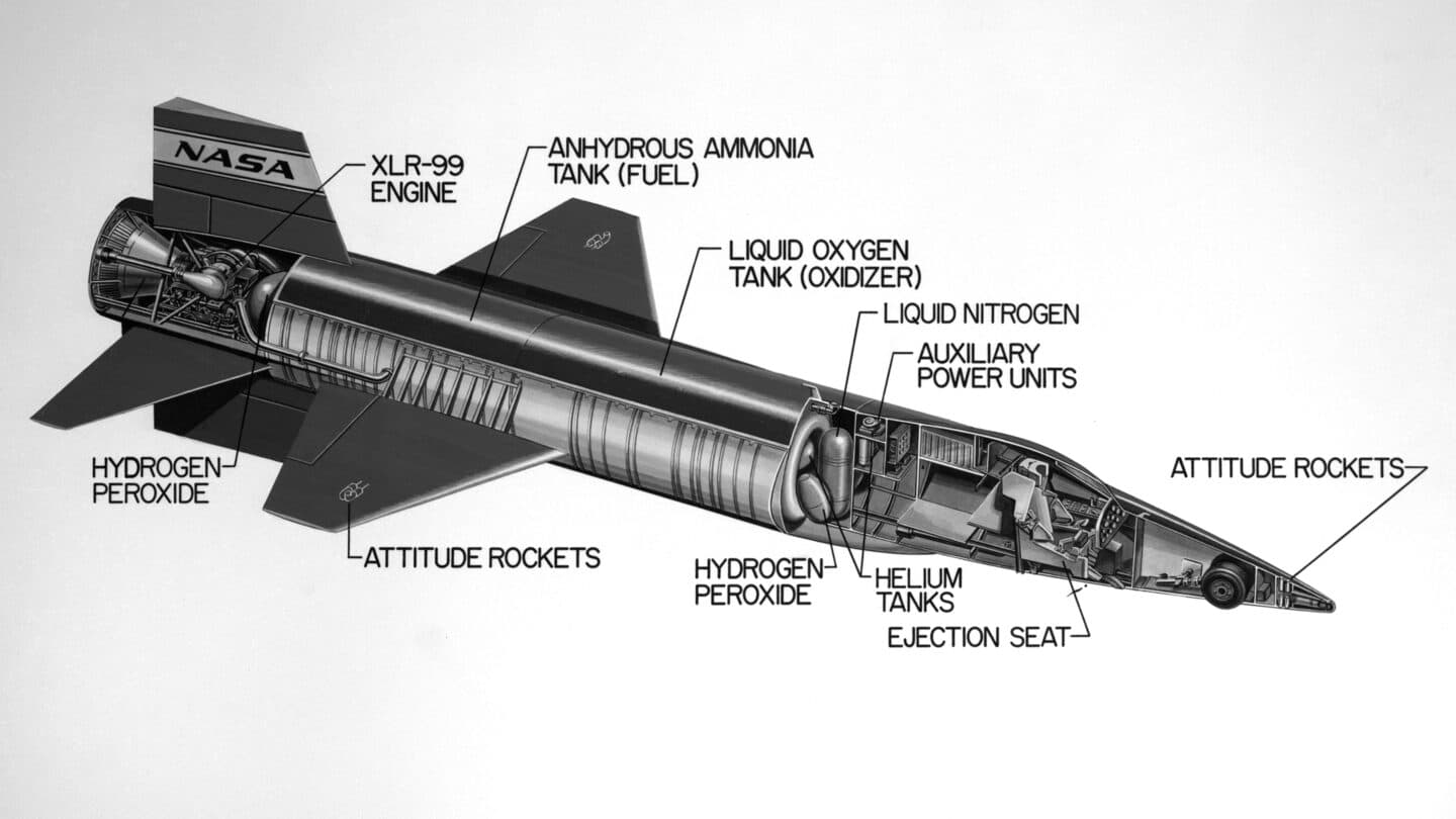
- Part of the outer skin removed to show what sits inside, with the rest left in place for context. The image at the top of this page is one.
- Isometric line art
- A three-dimensional view drawn with the three axes 120 degrees apart, so measurements along each axis share one scale. Clean lines, no perspective, and readable at small sizes: the default style of maintenance manuals.
- Locator view
- A simple view of the whole product with the area of interest marked, placed before the detail so a technician knows where on the aircraft, vehicle, or machine the task happens.
- Schematics and diagrams
- Symbolic rather than pictorial: wiring, hydraulic, and system diagrams that show how things connect, not what they look like.
- Photographs and renders
- Useful for identification and for showing a real installation, but they carry detail the task does not need and are hard to revise when the design changes.
Diagrams have their own conventions and their own manual in aviation; see our explainer on the wiring diagram manual.
Callouts
The Rules Live in the Small Print
Most rejected figures fail on callouts, not drawing. Military standards have spelled the rules out in detail. An older revision of the DoD style and format standard, MIL-STD-38784A, required callouts set electronically in upper case, numbered exploded views in disassembly order, gave a callout inserted at a later change the preceding number plus a decimal, and did not allow leader lines to cross. The interactive manual specification MIL-DTL-87268D asked for leader lines in a different width from the drawing, straight where possible or with a single 45-degree bend. The current MIL-STD-38784 is Revision C, so check the revision your contract cites before you build a style guide on any of this.
Numbers instead of words are also a translation decision. A figure carrying index numbers is the same in every language; only the key or the procedure text changes, and that text can be written in Simplified Technical English and translated with the rest. Words drawn into the art have to be found, translated, and redrawn for every language and every revision. The same logic keeps safety messages out of the art: a warning or caution belongs in the text, where it can be managed and found.
Formats
Draw Once, Publish Everywhere
Line art belongs in a vector format, which stores lines rather than pixels and stays sharp at any zoom. Aerospace and defense standardized on CGM, the ISO/IEC 8632 Computer Graphics Metafile, and its web profile WebCGM (a W3C Recommendation since 2010 in its 2.1 version), which adds the linking that makes interactive manuals work. SVG, the web's own vector format, serves the same role in many newer pipelines. Photographs stay raster. Our vector or raster explainer covers which belongs where.
The linking is the reason format matters more than it seems. In an interactive manual, a part in the figure is a hotspot carrying an identifier: select it and the viewer opens the parts entry or the procedure. Flatten the library to PNG and every one of those links is gone, along with the sharpness. The same goes for charts and tables pasted as pictures, a habit our piece on pasted charts takes apart.
S1000D
Illustrations as Managed Objects
S1000D treats each illustration as its own object with its own identifier, the information control number. Data modules point to a figure by its ICN, so one illustration can be revised once and reused in every data module that shows it. Which graphic formats a program accepts is set in its business rules and BREX, not by the specification for everyone. Our ICN explainer covers the identifier and the ICN metadata file.
In a conversion, illustrations are usually the slowest stream. Every legacy figure needs an ICN, callouts checked against the new text, and often a redraw to the program's style rules, so it pays to plan illustration as its own workstream from the start.
Software
From the CAD Model, Not From Scratch
Technical illustration software falls into four groups: general vector drawing programs, dedicated technical illustration packages built around isometric drawing and callouts, tools that generate 2D line art from 3D CAD models, and CAD systems themselves. The third group has changed the work most. Starting from the engineering model means the geometry is right by construction, and when the design changes the view can be regenerated rather than redrawn.
It does not remove the illustrator. Someone still chooses the view, removes the detail the task does not need, explodes the assembly in a sensible order, sets line weights and callouts to the style rules, and assigns the identifiers that make hotspots work. When choosing tools, judge them by their output first: whether they write the formats your contract or business rules require and keep those identifiers intact through every revision.
FAQ
Questions We Hear
What is technical illustration?
Drawing made to explain how something is built, operated, or maintained, rather than to look good. A technical illustrator removes every detail the reader does not need for the task and keeps every detail they do, so the result is accurate to the engineering and readable at a glance. In technical manuals that usually means line art: exploded views, cutaways, locator views, and diagrams.
What are examples of technical illustration?
The exploded view in a parts catalog, the cutaway in a systems description, the locator view at the start of a removal procedure, the wiring diagram in a wiring manual, and the step-by-step line drawings in an assembly instruction. Each style answers a different question: what parts are there, what is inside, where is it, how does it connect, and what do I do next.
Why do technical manuals use line art instead of photographs?
Line art shows only what the task needs, stays sharp at any size when kept as vector, reproduces cleanly in print and on screen, and can be edited when the design changes. A photograph shows everything, including dirt, lighting, and parts that do not matter to the task, and has to be retaken rather than edited. Photographs still earn a place for identification and real-world context.
What software is used for technical illustration?
Four kinds of tool cover most of the work: general vector drawing programs, dedicated technical illustration packages built around isometric drawing and callouts, tools that generate 2D line art from 3D CAD models, and the CAD systems themselves. The deciding factors for manuals are less about drawing features than about output: whether the tool writes the formats your contract or business rules require (often CGM or SVG) and keeps hotspot identifiers intact.
What is a callout in a technical illustration?
A label pointing at a part, joined to it by a leader line. Manuals often use index numbers rather than words, keyed to a parts list or to the steps of a procedure, which keeps the drawing free of text and the same in every language. Military standards have set detailed rules for them: an older revision of the DoD style standard, MIL-STD-38784A, numbered exploded views in disassembly order and did not allow leader lines to cross.
How do you learn technical illustration?
Through three skills more than any course: reading engineering drawings and models accurately, drawing in projection (isometric especially), and knowing the rules of the standard you deliver to, because a callout or line weight that breaks the style guide is a rejected figure. Tool training comes last. Most illustrators in technical publications learn the standards on the job, from the style guide and business rules of the program they work on.
Should manual illustrations be isometric or 3D?
It depends on what the reader does with the image. An isometric illustration is a fixed two-dimensional drawing of a three-dimensional object, with no perspective, chosen by the illustrator to show exactly the view the task needs. It prints cleanly, reads at small sizes, and gives every reader the same figure to cite and review. A 3D view is the model itself, which the reader can rotate and section on screen. It suits electronic delivery and exploration, but it needs a viewer and a format the contract accepts, and it gives a printed page nothing to show. Many programs keep the 3D model as the source and derive the isometric line art from it.

Get In Touch
Moving an Illustration Library?
We carry illustration libraries through conversion with their callouts, hotspots, and sharpness intact, and deliver them alongside the text through the Content Portal.